

After doing a little research I decided this too will become a DIY project! There is no soldering required however this is a little more technical than my usual construction projects. If you are into building electronics and are in need of a good 110VAC temperature controller then this is a fun and easy project. Also, this temp. controller could be used with a fan to cool when it starts to get too hot. If you are not so handy with electronics and are in need of a device like this, then feel free to contact me.
So lets get started. First I will admit, this is not the cheapest project and probably could have been done for even less money if I used a plain single-gang box with a couple cables and wire nuts, however, if something's worth doing, it's worth doing right...
The Parts:
| # | Part | Source | Qty. |
| 110V AC Temp. Controller Module | Ebay (earlybirdsavings) | 1 | |
| HM243-ND | Project Box - ABS | Digi-Key | 1 |
| Q209-ND | AC Receptacle | Digi-Key | 1 |
| Q227-ND | Power Outlet | Digi-Key | 1 |
| 401-1307-ND | Rocker Switch - Lighted | Digi-Key | 1 |
| WM6897CT-ND | .187 Quick Connector | Digi-Key | 6 |
| A27824CT-ND | .25 Quick Connector | Digi-Key | 3 |
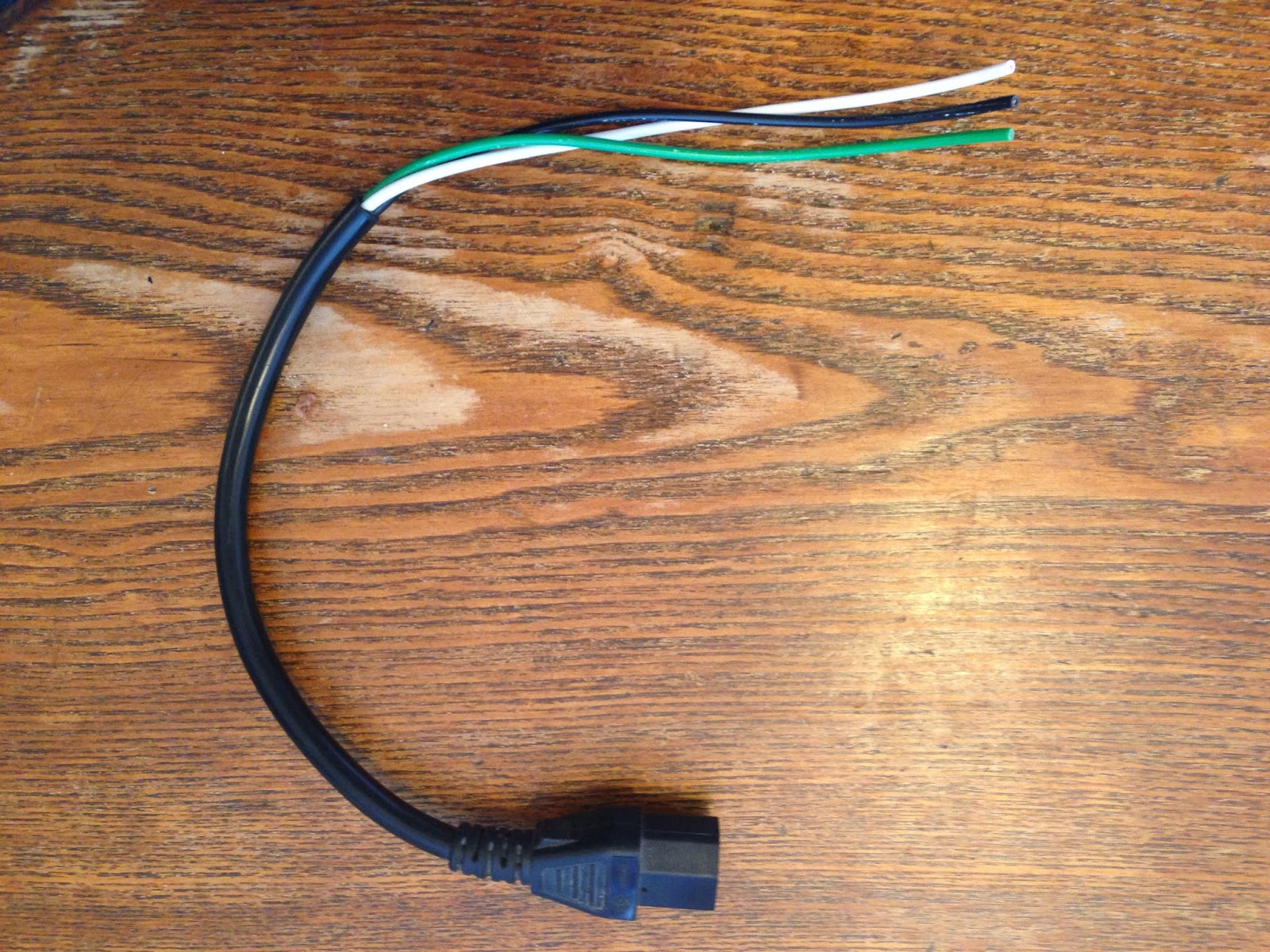
| 5292 | 6' 14AWG Power Cable | Monoprice.com | 1 |
SAFETY NOTICE!
This project involves high voltage electricity and can be extremely dangerous, please use caution! Double and triple check all of your connections before applying power. Never plug your project into the wall with the box open. Unplug immediately if there is any smoke or popping sounds.
|

|
 The Controller |
| The first thing to do is cut the openings in the project box for all of the different components. Using a Dremel or similar tool is highly recommended since the plastic is thick and using a blade can be dangerous. If you do not have a Dremel or rotary tool then a series of holes made with a drill and bit in combination with an x-acto blade should do the trick. (Careful not to cut yourself!) | 
|
| On the front panel (the taller side) I cut a rectangle and square for the controller module and the AC Outlet. On the right side, towards the center I drilled a hole with a notch towards the front for the illuminated switch. Around the other side I drilled a small hole just big enough for the temperature probe to go through. You could buy a rubber gromite for this but since I was unsing this one for myself I just put some silicon on the inside instead. | |

|
 As you can see, the cuts do not have to be perfect, mine are not. |
| Next I took the small orange brackets off the control module and started fitting the switch, AC Outlet and AC Inlet. It took a little tweaking with razor to get all of the components to fit, you want to start out a little small and shave a bit to get a nice snug fit. If you find the hole you cut is a bit too large then try to silicon the component from the inside so it doesn't move around. You will want to wait on installing the control module until you have added all of the wires - since you will not be able to afterwards. | |

|
 I've found if the button is too snug it will not switch easily if at all - place it and test. |
| For the wire inside the controller I used pieces from an old computer cable I cut in a different project. Strip the black jacket and you have nice stranded copper cable that is easy to work with and rated for high voltage. I started by eyeballing lengths and cutting/stripping the wires that will attach to the control module (not the green ground wire). | |
|

|
| Next I wired the controller, you can see the power is jumped from the input to the switch and the other side of the switch will go out to the AC Outlet. Once it is all wired, the cover can be screwed back on and the module can be installed into the project box. after inserting the module into the box about half way, install the orange tabs so it can be locked into place. | |

|
 You can see all of the components are in place and ready to be wired. |
| Since I used quick connectors for the plugs and switches, there is no soldering required, just crimping (Make sure to use a proper connector crimp tool so you do not have loose connections). Depending on the gauge of wire used, it can be difficult to insert two cables into one connector so plan accordingly, if all else fails, use a wire nut. Since I already installed all of the components into the box and space is tight - I used needle nose pliers to slide the connectors onto the tabs, starting with the lowest connections first and working my way up. | |

|
 Take your time and make sure every connection is correct as you work your way up. It is best to use properly color coded cable for easy identification. |

|
 The green ground wire just passes from the input to the output since the module does not require a ground |
| After carefully checking over your connections it is finally time to screw the bottom on and plug it in! If all was properly connected you should be ready to set the temperature and slew following the lovely instructions provided with the module (note a bit of sarcasm) and you are ready to install the temperature controller in your brooder or coop! Hope you enjoyed this project, I sure did! I am currently working on detailed plans including a wiring diagram that I will be selling for $1 - Stay Tuned! | |

|

|


2 comments:
Cool! Very neat finish to your project.
I used a very similar temperature controller to replace the crappy wafer temperature controller on my Hovabator incubator:
http://green-change.com/2013/11/16/hovabator-incubator-fridgemate-hack/
Thank you! Iv'e already put this thing to use and it is working great!
Thanks for the link, you're Fridgemate hack is awesome!! That wood box you used is perfect! I wish I could find something like that in my area.
Post a Comment